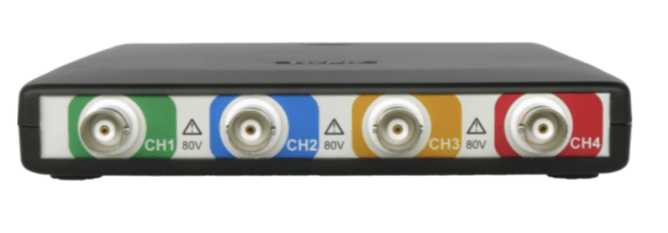
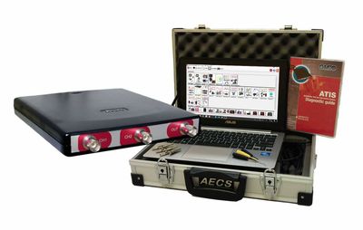
Imagine having an affordable tool that could fulfil many different tasks that would otherwise require expensive equipment. Plus it is extremely quick to set up which saves time. Sounds too good to be true for sure but read on....
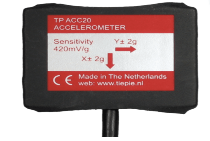
ATS oscilloscopes can drive a useful accessory called a G Force sensor. Simply plug the multi pin connector into the rear of any multi channel ATS scope, set either the X or Y axis shown on the sensor itself in the direction of the acceleration force you want to measure, connect your leads onto the measuring channels of the ATS scope and you are ready for business.
If you need to know if a vehicle is down on power and the thought of dyno testing is cost prohibitive, a G Force sensor can assess the power of the vehicle and create a credible report.
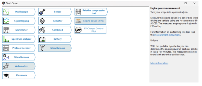
Simply open the measuring software, enter the weight of the vehicle to the software, find a flat piece of road of suitable length and drive from stationary to 3rd gear as fast as possible, then release the accelerator and count to 5 before braking.
A report will be created from the test that can be saved and compared to what is listed as the power rating of the vehicle. Two similar vehicles could also be compared.
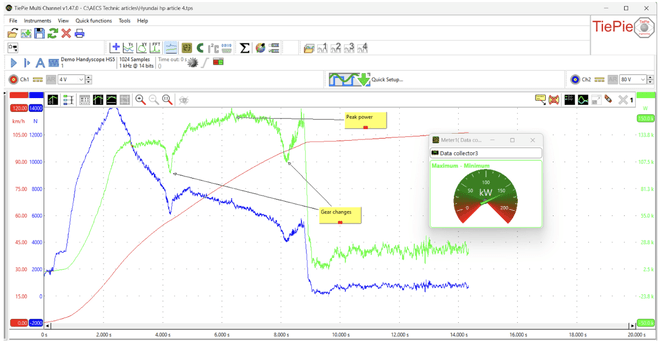
In the below graph you can see the 1-2 and the 2-3 gearshifts in the green trace of scope recording. Peak power is not applied in first gear so as to not excessively burn up the tyres and load the driveline. In second gear an extra 25 kw is applied by engine, peaking at just above 150 KW on this late model Hyundai iload van which by the way took around 15 minutes of work
Locating misfiring issues in engines is also a task G Force sensors excel at. Using the ATS scopes we often create crankshaft speed delta lines. A delta line is the actual crankshaft speed per rotation of the crankshaft which is created by connecting to the vehicle's crankshaft speed sensor and using the mathematics of the ATS scope software. This shows the effect of compression/power strokes and makes finding mechanical issues or energy delivery issues very easy.
You can create the same patterns by sitting the G Force sensor on top of your engine, measuring the rocking of the engine under compression in one direction/then another on power strokes.
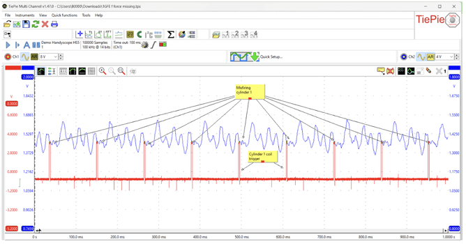
On your ATS scope one channel will measure the G Force sensor. On another channel you can measure a reference point such as fuel injector or coil number one. This enables you to locate, via firing order, which cylinder/cylinders are giving issues.
Very quickly and with little effort you can locate an engine misfire. The G Force sensor also comes with a trigger button which you can use to freeze the scope recording as you are driving the vehicle to locate an intermittent misfire.
These are just some of the ways you can apply ATS scopes to solving what would otherwise take considerable time/effort. This equipment can eat problems for lunch.
With the support of AECS Equipment and our technical support we can make a scope with accessories a money earning, problem solving machine!
https://www.aecs.co.nz/automotive-scopes/

