A recent tech support case dealt with an early 2000’s Ford XR8 with what looked initially to be a straight forward ignition coil issue. As this case played out we required the awesome capabilities of the ATS scope. In this particular case we use the ATS scope which is an electronic tool to find electrical and mechanical problems...
Problem presented to the tech support team
Ford XR8, early 2000 model year with a misfiring engine. Owner has been carrying out his own attempts at remedying the situation and holds an honours degree from Google search/owners forums. There is a boot full of parts that should fix the problem, the owner enthusiastically stated during booking in the vehicle. Although not when he has fitted them for some reason the workshop noted.
The workshop carried out some preliminary tests such as road test and scan. They noted a definite misfiring of the engine, probably multiple misfires. A scan of the vehicles engine control module was carried with the workshops Launch Auscan scan tool but revealed nothing particularly definite.
These fault codes were very likely caused by the unburned fuel passing the oxygen sensor and flooding the catalytic converter due to the misfires our technician was experiencing. They could also be ruined by all the unburned fuel yet as well.
Where to next ?
The AECS Equipment tech support team could go deeper with this workshop as they had invested in a ATS scope which could carry out the necessary measurements of the vehicles ignition system to properly test it.
This particular engine only uses two ignition coils to run the eight cylinder engine, so seeing these were so accessible the tech team suggested measuring both ignition coils to see how well they were igniting in the engine. A very simple and quick way to assess an ignition system is to measure how long it can sustain an arch over the spark plug in the engine. Any issue will show up such as power/ground issues or wear in spark plugs. It will show up as a shorter than required spark duration.
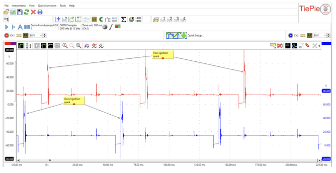
The following ATS scope recording was shared and assessed. In the above primary ignition system recording of the second of the vehicles two coils, we can see in the top red trace two spark events where there is a very short duration of spark across the spark plug. These two events measured around 700 us (micro seconds). A general rule of thumb for ignition systems a spark must be at least 1 milli second at idle. Many modern ignition systems are 3x times this duration and is one of the reasons you need platinum on your spark plug electrodes as these long duration arches cause rapid wear on lesser materials. So lots of fuel will be unburned (misfire) due to short spark length. . Also of concern in this recording is the high firing line of these two spark events which indicates high resistance in the igntion system secondary circuit(spark plugs&leads).
On inspection the spark plugs were found to have very large gaps and wear in electrodes.
These were replaced along with the ignition coil which had a short circuit in the coils windings.
The vehicle ran much better but still had a misfire. Now we had what felt like a random single cylinder misfire.
Next step…go deeper
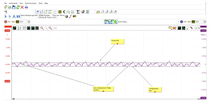
We need to see how our engine is performing mechanically and energy delivery wise. The measurement the support team suggested shows misfires like UV dye shows refrigerant leaks. So the workshop used the ATS scope to create an RPM line. This is created by measuring the vehicles crankshaft speed sensor and then adding a cylinder reference such as an ignition coil trigger pulse or fuel injector pulse. This will give us a way of following the firing order of the vehicles engine to identify each cylinder in the RPM line we will create.
However the workshop had a 2 channel scope and would need a 4 channel scope on this particular vehicle. So we made the RPM line of actual stroke by stroke crank speed without a reference, to get at least an overall view of our engine system.
The software of the ATS scope can use its software’s mathematics just the same as a vehicles engine ECU does to calculate engines crankshaft speed on every power and compression stroke of the crankshaft.
The RPM or Delta line can also be analysed by the scopes software further. A Differentiate measurement can be carried out on the RPM line which essentially measures the slope of the acceration/deceleration line on the RPM trace to show the differences in these two speeds.
Instantly we can see in the above recording that we are getting uneven compression(the lower horizontal cursor) as well as some power strokes not reaching the top cursor.
Another measurement of the vehicles coils was carried out and was found to have a faulty new ignition coil.
The lower compression was now our last issue to solve. Broken piston rings, piston damage, cylinder wall damage, valve damage or not enough clearance to camshaft, damaged valve springs, intake or exhaust blockage could cause this issue. However for an intermittent issue the most likely cause would be valve springs. The valve covers were removed to locate 1x broken valve spring and loss of tension in others.
After informing the vehicles owner, valve springs were replaced and now our vehicle is running great.
The oxygen sensor and catalyst efficiency fault codes cleared with the now properly running engine.
When the owner picked up the vehicle he shared that the vehicle was once badly overheated due to a radiator failure which was likely the cause of the valve spring issues.
The diagnosis of this job took less then two hours and the technician and workshop were able to progress through the repair with a high degree of confidence in their decisions.
This is the kind of information a quality ATS diagnostic scope can deliver . Our support team enjoys seeing the great results these give automotive business and their clients.
Head to our website and see our full range of ATS scopes here


